Van Solar Install: Complete 2025 Guide (With Wiring Tips)
- Jun 19, 2025
Step-by-step camper van solar installation from panel mounting to wiring. Size your system, avoid costly mistakes, and get power in one weekend.
Table of Contents
- High Level Solar System Design Orientation for Beginners
- Selecting Solar Panels for Your Camper's Solar System
- Mounting Solar Panels to Your Vehicle: Solar Panel Installation Options
- A Guide On How to Connect Multiple Solar Panels
- Sizing Fuses for Your Solar Panels
- Sizing Wire for Your Solar Panels
- Getting Power From the Roof Into the Van
- Sizing Wire for the Electricity Leaving the Solar Charge Controller
- Adding Fuses to Protect Your Wiring and Electrical Components
- Connecting Your Solar Charge Controller to the Batteries
Van Solar Install: Complete 2025 Guide (With Wiring Tips)
Adding a solar panel system to your DIY camper van provides an enormous amount of freedom. With solar panels, we can charge our batteries off the grid and roam freely. But if you’re new to working with electricity, choosing your solar panels, wiring, fuses, and solar charge controller for your solar setup can feel daunting as you begin planning your solar electrical system! If this describes how you feel right now, then this guide is for you.
By the end of this guide, you’ll understand the purpose of and how to size all the components related to your solar power system, from sizing your panels, determining wire gauges and fuse ratings, and selecting an appropriate solar charge controller for you needs.
High Level Solar System Design Orientation for Beginners
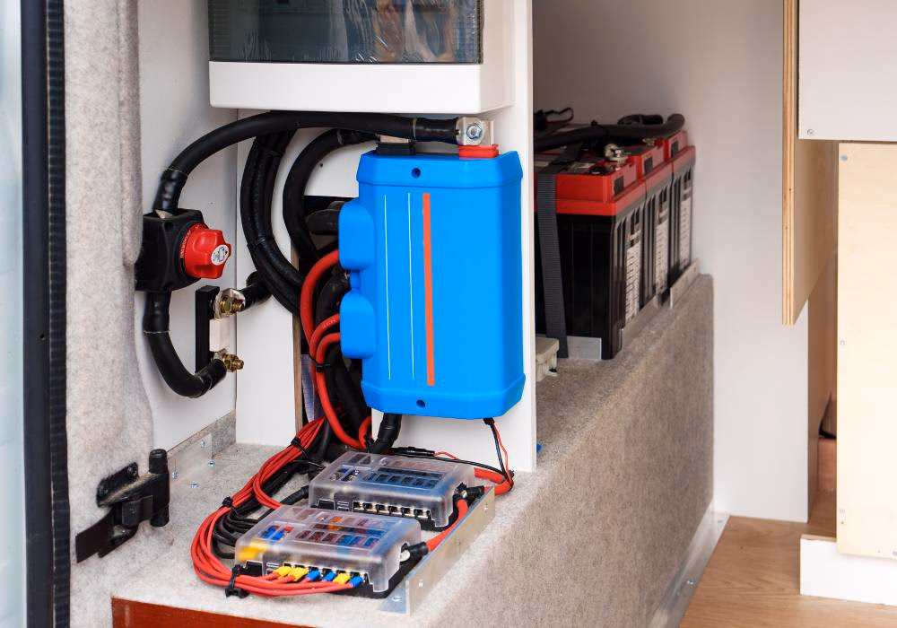
At the highest level, your solar panels harvest solar energy to generate electricity and pass this generated power along a wire at a current (amps) and voltage determined by the solar panel itself. This wire, running from the solar panel array, is then connected to a solar charge controller. The solar charge controller converts the voltage coming from the solar panels into a range your van’s auxiliary battery bank can safely accept, such as 12 or 24 volts.
Fuses are installed on the wires to protect your electrical components from damage if a short circuit were to cause a surge of energy to pass through the wiring. A manual shutoff switch is often installed, so users can turn off the flow of electricity between the solar panel array and the solar charge controller. Once you read the article and understand your needs, use the calculator below as a guide for your solar design:
Maximum Inline Fuse Rating
1 Amps
Amp Hours expected from this configuration
Recommended Wire Gauge From Panel to Solar Charge Controller:
14 AWGThese solar charge controllers are suitable for the selected solar panel, select one:
Recommended wire gauge from solar charge controller to busbar
Minimum fuse size at bus bar
A safety note:
This calculator is designed for a 12V battery bank.
A note on wire selection:
All wire sizing is based on the Marine Grade® Boat Cable by Ancor Wire & Cable Technical Data Sheet and assumes a desired 3% voltage drop. We highly recommend using this brand if you are following the recipe created by this calculator, as other brands may require different wire sizing.
Selecting Solar Panels for Your Camper's Solar System
The primary concern when selecting solar panels is whether they will fit on the van's roof and whether they can provide enough power to your battery bank to meet your energy needs. As a simple rule of thumb, we recommend your solar panels provide one watt of power for every amp hour of capacity in your auxiliary battery bank. So if you plan to install 400 Amp Hours' worth of batteries, then you should plan to install 400 watts worth of solar panel power capacity.
Solar panels are marketed by their rated power, so the panel might be sold as a 200-Watt model. This is the wattage value you’d use to figure this out. This value is also referred to as the Pmax value. So, in this example, two 200-Watt model solar panels would be considered adequate for a 400 Amp Hour battery bank because when combined the two panels provide 400 Watts of power.
If you’re not yet sure how much battery capacity you’ll need (determining this value is where your electrical design journey should begin), take a look at our energy demand calculator below.
In addition to wattage, the physical dimensions of the solar panels matter because they’ll need to fit between the runners on your roof rack. And if you plan to have a Maxxair fan (or two) or an air conditioner mounted on the roof, you’ll need to work around these, as well. So get up on your roof and measure the available space before you make any purchases.
Mounting Solar Panels to Your Vehicle: Solar Panel Installation Options
There are several options when mounting panels to your camper van's roof. The best option is mounting the panels to a roof rack. This option is best because most roof racks can be mounted without putting holes in the roof. Mounting panels directly to the roof will require screwing brackets into the roof itself. The more holes in the roof, the more likely you are to get a leak over time.
We have seen DIY van builders that have taped flexible panels to their roofs, but we don't recommend this, as we have also seen follow up from these builders that the panels flew off while driving down the interstate.

Hey! We used the Unaka Gear Co. roof rack to mount our solar panels. And it made mounting our panels super easy. We talked to the builders over at Unaka Gear Co. and got you a discount if you use the coupon code BUILDTOROAM at checkout.
Visit Unaka Gear Co. Store For 10% Off Your Purchase
The framing on solar panels will generally have pre-drilled holes. These are used to mount brackets to the panel. The brackets can then be bolted to the roof rack or the roof itself.
A Guide On How to Connect Multiple Solar Panels
Let’s say you’ve decided on mounting two solar panels to your van’s roof: You have two options for how you wire these together. And this decision impacts the wire size and solar charge controller size downstream.
But first, let's cover some important technical details. We know your solar panels produce electricity as they harvest sunlight, and that this electricity is passed along at a voltage and amperage determined by the panel. Every solar panel comes with a data sheet that tells you the maximum voltage and current your panels will produce. Knowing the maximum voltage and current will help you safely size your solar charge controller and wiring. Take a look at the solar panel datasheet below:
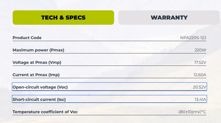
The maximum voltage your solar panel will produce is stated in its VOC value, or the open circuit voltage value. The maximum current produced by the solar panel is stated in its ISC value, or the short-circuit current value.
These are not the values you will see when monitoring the panel output in real world conditions, but they are the values to use when designing your solar system, since they represent the theoretical maximum outputs that the wire and solar charge controllers must handle.
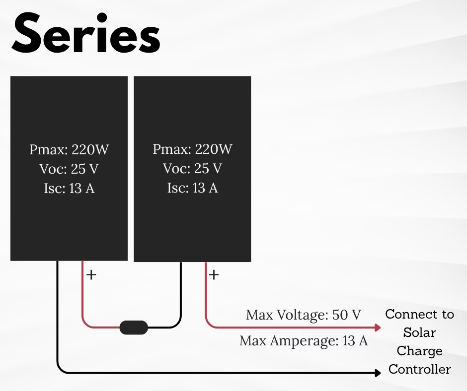
Solar Panel Wiring Options: Wiring Panels in Series
Wiring two solar panels in series causes the voltage produced by the panels to add together. When wired in series, multiply the VOC value by the number of panels to determine the maximum voltage produced by your solar panel array. So two solar panels with a VOC of 25 Volts each, when wired in series, will produce up to 50 Volts. This value is important when sizing your solar charge controller.
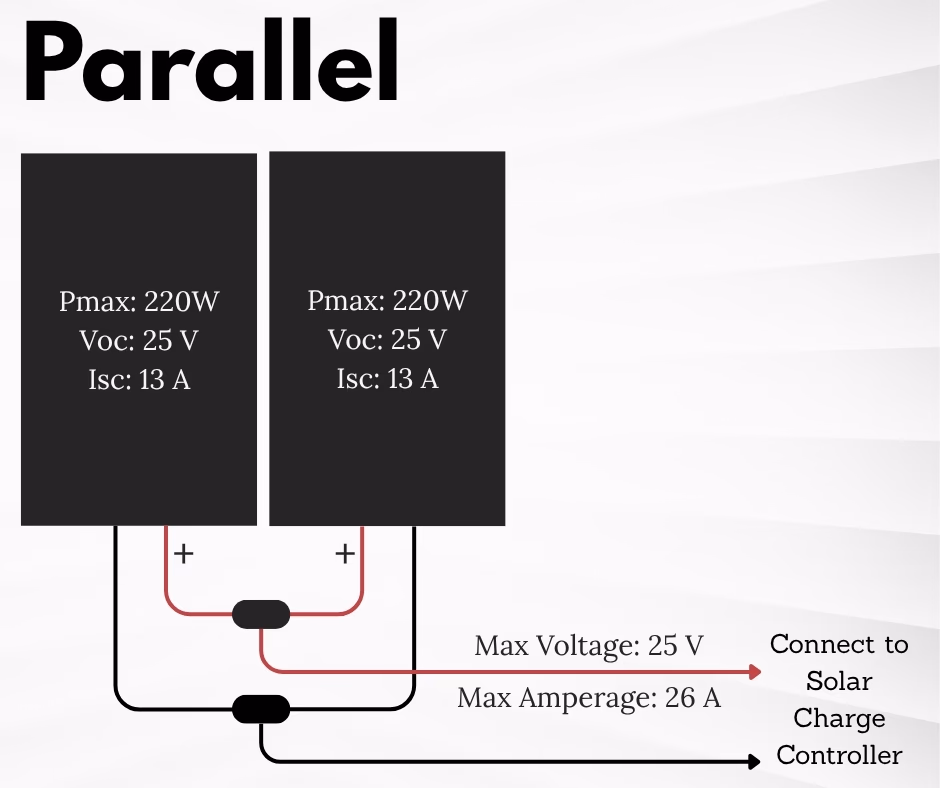
Solar Panel Wiring Options: Wiring Panels in Parallel
If you wire the two solar panels in parallel, the current of the two panels add together. When wired in parallel, multiply the ISC value by the number of panels to determine the maximum current produced by the array. If the ISC of the solar panel is 13 Amps each, an array of two solar panels wired in parallel will produce up to a maximum of 26 Amps. This value is important when sizing your wire and when sizing your solar charge controller.
Solar Panel Wiring Options: Tradeoffs of Wiring Series Versus Parallel
So what’s the tradeoff between choosing parallel or series wiring? Why would you choose one option over the other? When the panels are wired in parallel, the current of the array is higher, so the wire running from the solar panel array to the charge controller will have to be sized larger to handle the increase in current. In this sense, it would be less expensive to wire the panels in series, as the wire would be thinner and therefore less expensive. But if the panels are wired in series, shading on part of the solar array will lower the power produced from the entire array.
Sizing Fuses for Your Solar Panels
In the data sheet where you find the previously mentioned values like ISC and VOC, you will also find a value called the Maximum Series Fuse Rating. The manufacturer determines this value based on what fuse size will protect the solar panel and its internal wiring. Since the majority of solar panel wiring comes with quick connect wire adapters known as MC4-style adapters, the easiest way to add a fuse to protect your solar panel is to add an inline MC4 fuse to the positive wire coming from the panel prior. The fuse should match the Maximum Series Fuse Rating from the datasheet.
There is debate about when these fuses are and aren't needed. But since they're cheap enough and can save your panel, we recommend adding them for peace of mind.
Sizing Wire for Your Solar Panels
Once you have your solar panel array selected and know how you want to wire it, you have enough information to select the wire size and solar charge controller.
If you're completely new to wire selection, check out our article Sizing Wire For Your Van Build: A Beginner's Guide to get oriented. It's an orientation to the principles of sizing electrical wire.
To size the wire connecting your solar panel array and the solar charge controller, you'll first need to know the length of your wire run between these two components. The length used in your calculations is the cumulative length of both the positive and negative wires added together.
In addition to the wire length, you need to know the current that will be carried by the wire. For this, use the ISC, or short-circuit current, value provided by the solar panel manufacturer. If you have more than one panel wired in parallel, multiply the ISC value by the number of panels.
Now that you know the wire length and current it will carry, you are ready to check the wire sizing chart. The chart below is made available by the marine wire manufacturer Ancor. Ancor knows the wires have an insulator rated to 105 degrees Celsius and that the wire is made from multi-strand tinned copper, so the chart accounts for these. Generic charts or online calculators might ask you these details.
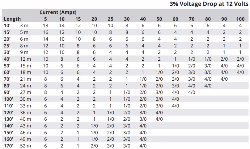
As you can see on the top right of this chart, the wire size recommendations are only relevant for 3% voltage drop in 12 Volt electrical systems. Disclaimer: It could be dangerous to use this chart for a 24V or 110V system.
If we know the wire run is 20 feet and the amperage running between the components is 25 Amps, we locate these rows and columns and find where they intersect to get the appropriate wire size, in this case the diameter is reported in AWG.
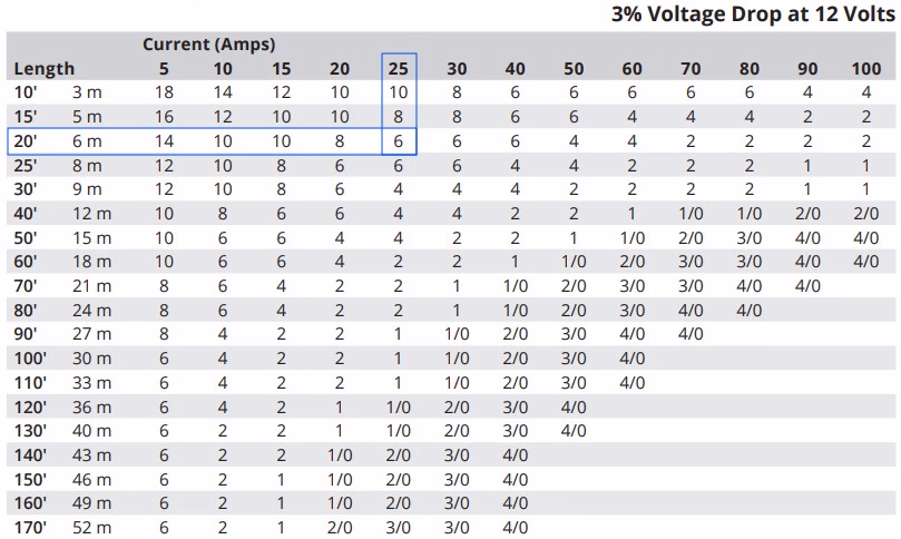
As you can see, the 20-foot length row intersects with the 25 Amp column at the value of 6 AWG. So we know that our wire needs to be sized as 6 AWG. In reality, we prefer to limit our panel wiring and selection to a range that results in 10 AWG wire selection. Our solar power calculator will do all of this for you. Try it out here: Solar Power Calculator
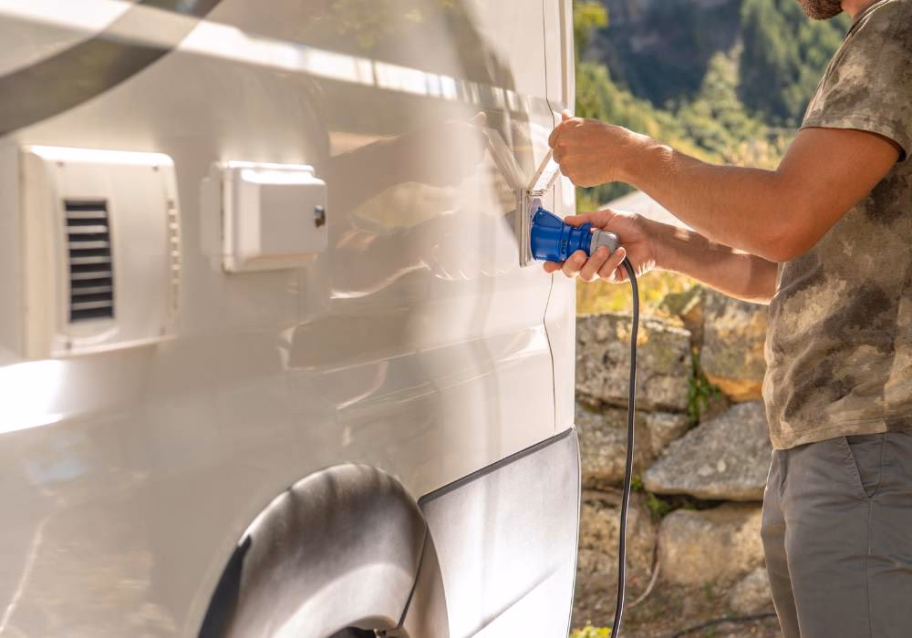
Getting Power From the Roof Into the Van
Once you have your wire size selected, you need to connect the wire to your solar panels and run it through the roof into the interior where it will connect to a shut-off switch and the solar charge controller.
Connecting Your Wire to Your Panel
Since your solar panels come from the manufacturer with MC4-style quick connect plugs on the solar cable, we recommend adding an MC4 plug to the wire you run through the roof. This requires a crimping tool and crimping the adapter's internal metal part to the exposed copper on the wire.
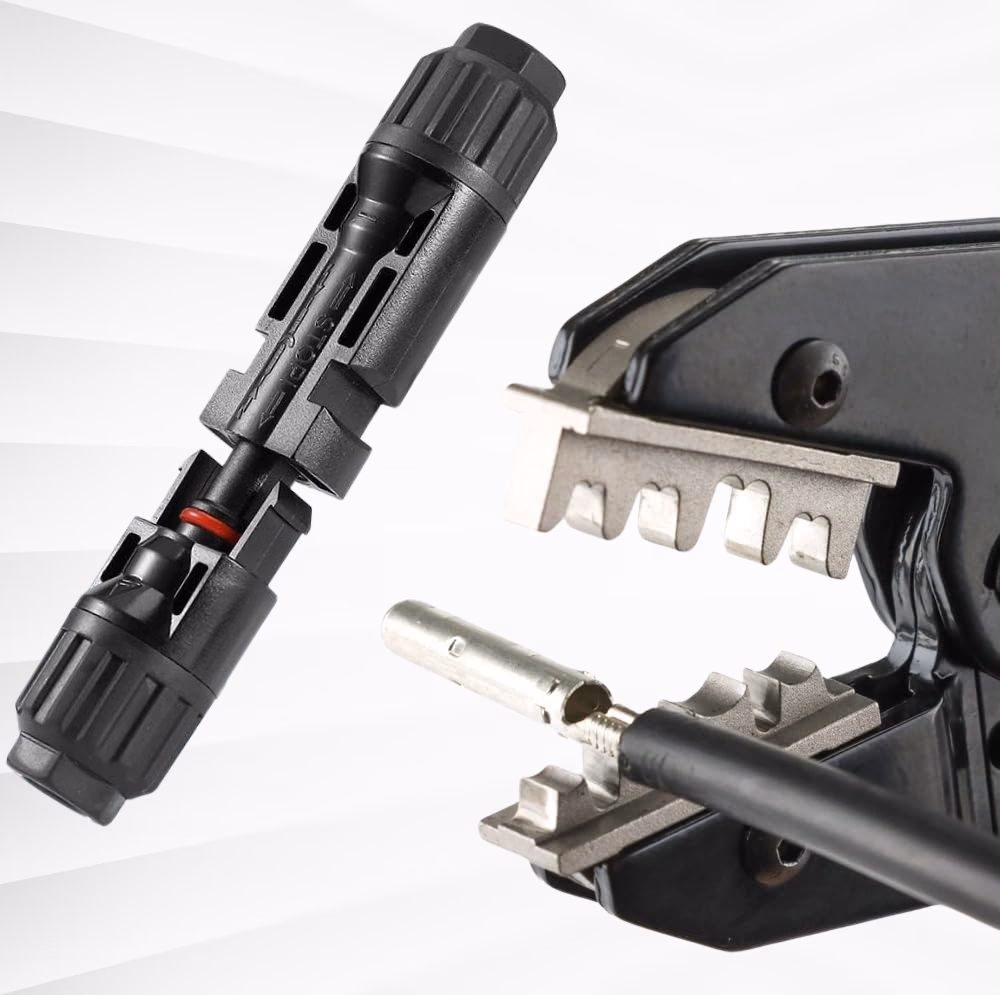
Slide the MC4 adapter's plastic section over the metal you just crimped over the exposed copper and connect it into the solar panel's MC4 connector based on how you've decided to wire your panels together.
Cutting a Hole in Your Roof
Cutting your first hole in the roof is scary. But this is required to run the solar power into your van's interior. But fortunately it's a super easy process. Locate where you want the wire to enter. Mark the location, and use a hole saw to cut your hole.

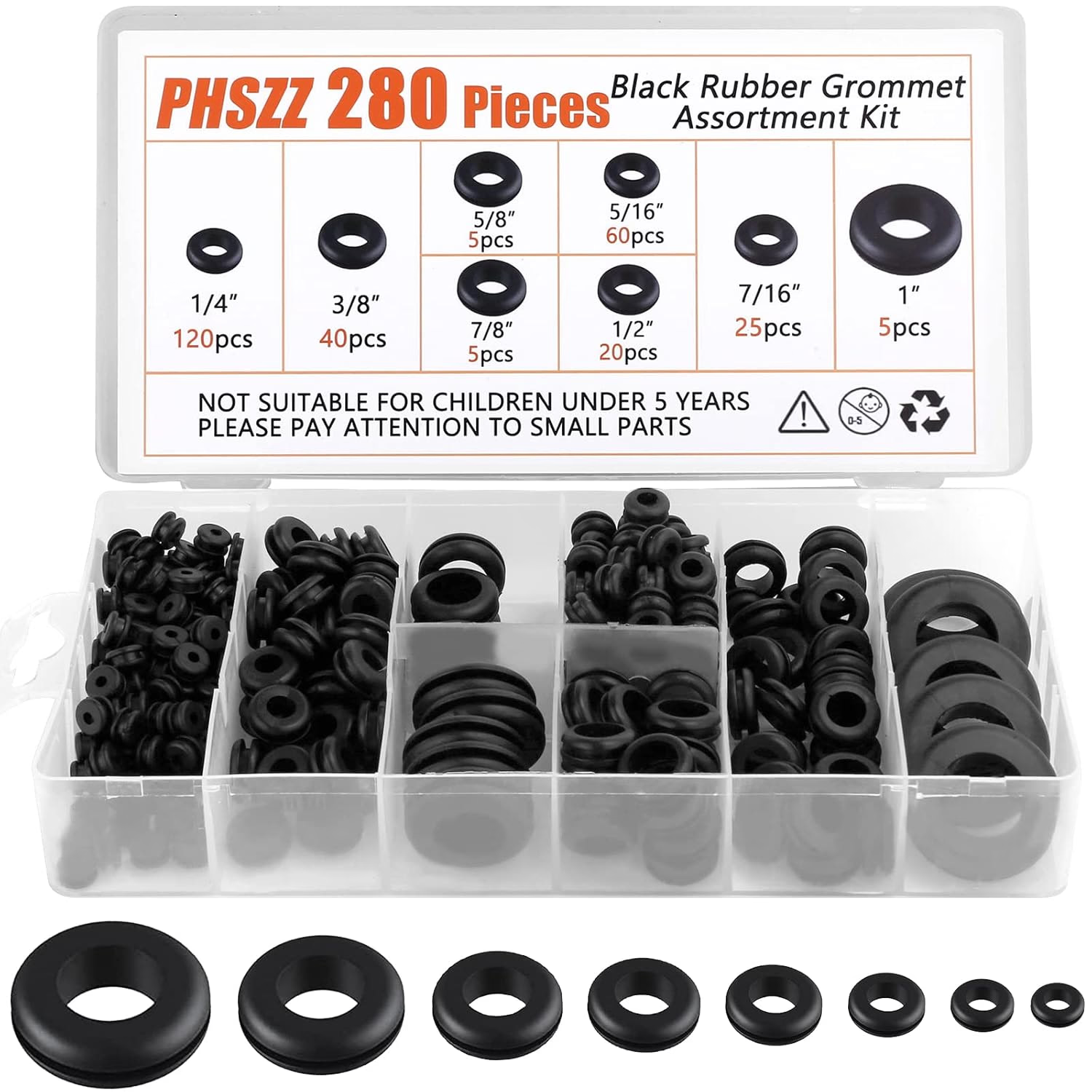
After you cut the hole, we recommend filing the edge to smooth out the rough metal edges. A simple metal file is all you need. Then apply an automotive primer to the exposed metal to prevent rusting. Additionally, we recommend gluing a rubber grommet to the opening to help protect the wires from rubbing against the metal and wearing down over time.
The size of the hole depends on the Cable Entry Gland you purchase. The cable entry gland is a cover you place over the hole, with a waterproof seal attaching it to the roof. If the gland does not come with a seal, we recommend Dicor Butyl Seal Tape.

Within the cable entry gland are two wire openings where you pass the wire before spinning the nut tight to make the opening watertight. A properly installed gland ensures the hole is entirely waterproof. We recommend running a bead of Dicor Self-Leveling Lap Sealant along the border of the gland to ensure waterproofing along the edges where the Cable Entry Gland meets with the roof surface.
Solar Power Shutoff
It's important to have a shutoff somewhere along the wire run. Why? Safety and convenience. There are times you'll want to work on your electrical system, and cutting incoming power from the panels will be required for safety. Or maybe the van will be in storage. Instead of disconnecting wires, you can simply flip a switch.
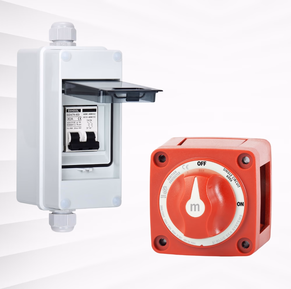
This shutoff can be a circuit breaker style or a simple shutoff and should be placed between the solar panels and solar charge controller.
The shutoff should be located somewhere convenient to access. If you plan to install a breaker style shutoff, read on in the fuse section below to safely size the breaker.
How to Select Your Solar Charge Controller for Your Campervan
For lithium batteries, we recommend MPPT solar charge controllers. Without getting too geeky, the MPPT controller are efficient and have emerged as a favorite for DIY van builders.
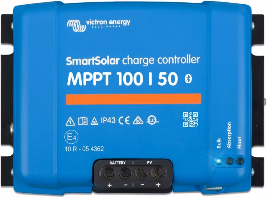
The solar charge controller has several values that you need to consider when making your selection. Consider the Victron solar charge controller datasheet below:
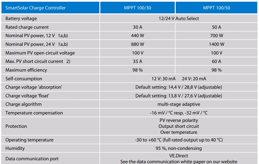
First, ensure auxiliary battery voltage compatibility. Many modern controllers will auto-detect whether your batteries are 12V or 24V and will work with either. But it’s important to check compatibility before making your purchase.
Second, the solar charge controller has a maximum voltage input. To determine how many volts are coming from your solar array find the solar panel, VOC, or open circuit voltage, value. If your panels are wired in series, multiply this value by the number of panels. If the solar charge controller is advertised as a 100V model, then the maximum voltage coming from the solar array must be below 100V.
Third, the solar charge controller has a maximum current input. To find the maximum current coming from your solar array use the ISC, or short-circuit current, value provided by the solar panel manufacturer. If you have more than one panel wired in parallel, multiply the ISC value by the number of panels. As a safety factor, multiply this value by 1.25. And your solar charge controller amperage rating must exceed this value. So if the current coming from the solar array is 26 Amps, we'll multiply this by 1.25 to get a value of 32.5 Amps. The solar charge controller rated amperage therefore must exceed 32.5 Amps.
Fourth, the wire openings are often limited to a wire diameter and smaller. The popular Victron 100/30 and 100/50 models can fit only 6AWG and smaller wires.
Sizing Wire for the Electricity Leaving the Solar Charge Controller
The wire leaving the solar charge controller will be larger than the wire coming from the solar panel array. This is because the solar charge controller will lower the voltage to match that of the auxiliary battery bank. This will increase the current, or amperage, passing to the auxiliary battery banks. And since wires are selected based on the amount of current expected to pass through them, higher current require a higher gauge wire to safely carry the current.
The easiest way to calculate the maximum amperage leaving the solar charge controller is to take the power rating of your panel or panels, for our purposes here, let’s say this equals 400 Watts. Now divide this by the voltage of your battery bank, let’s say in this example it’s a 12V auxiliary battery bank. 400W / 12V = 33.3 Amps.
Consult the wire manufacturer's wire sizing chart to find a wire gauge that can safely handle this amperage.
Adding Fuses to Protect Your Wiring and Electrical Components
Fuses protect your wires and electronic components. To size your fuses properly, you must know the maximum current that will be passing through the wire you will be adding your fuse to. To size the fuse, take the maximum expected current passing through a wire and multiply this value by 1.25. The fuse should be as close to this value as possible.
So if you are expecting 33.33 Amps to pass through the wire, your fusing calculation will be 33.33 Amps x 1.25 = 41.7 Amps. The fuse you will select will be either 40 or 45 Amps. So if the current passing through the wire exceeds the expected amperage due to a short circuit, the fuse will stop the flow of electricity and protect any wire or components down stream.
Fuses and breakers come in all sorts of shapes and sizes, and you can choose whichever style meets your needs. Ensure the fuse is rated for the voltage of your system. And since these are for safety, we highly recommend purchasing from a reputable brand. If you are unsure if the fuse will meet your needs, reach out the manufacturer prior to your purchase.
Connecting Your Solar Charge Controller to the Batteries
The wire leaving the solar charge controller will power the batteries. Practically speaking, the wire will likely land on a busbar, which is functionally an extension of the battery post. This wire must have a fuse on it. The fuse should be sized 25% greater than the expected max amperage passing through the wire. In the example above, the max expected current was 33.3 Amps. 33.3 x 1.25 = 41.625 Amps. Find a fuse rated for the voltage of the auxiliary battery bank and, since fuses are often in intervals of 5, rated to either 40 Amps or 45 Amps. In this specific case, the likelihood of your solar panel array reaching its maximum power output is unlikely outside of the laboratory, so rounding down to 40 Amps would feel fine and provide adequate protection.
Beyond Solar System Design: Inverter selection, DC-DC Charging, Battery Monitor, Battery Bank, and Energy Input Monitoring
With the solar panels charging your battery bank, you'll have access to DC power which is great for lights and some appliances. But there's still some work required to finish your campervan's power system. In future articles, we will be discussing how to select and install an inverter, how to install DC-DC charger so you can power the auxiliary battery bank from the alternator, and much more. Please sign up to our newsletter if you'd like to learn more.