Van Inverter Guide: Size, Install, and 3 Integration Options
- Sep 3, 2025
Choose the right inverter size for your camper van—pure vs. modified sine, size, wiring, fuses, and step-by-step install tips for safe off-grid AC power.
Table of Contents
- How to Size Your Power Inverter For Your Camper Van or Truck Camper
- What Type of Inverter Do You Need: Pure Sine Wave Inverter or Modified Sine Wave Inverter
- How To Select and Properly Size Your Campervan Inverter
- How to Install Your Inverter
- How to Power 120V AC Devices With Your Inverter
- Powering a 120V Distribution Panel From an Inverter
- Integrating Your Inverter With Shore Power or a Generator
Van Inverter Guide: Size, Install, and 3 Integration Options
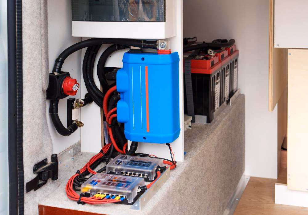
Some electric devices and appliances you’ll bring with you on the road can only be powered from your typical home wall outlets, and not the 12V or 24V DC power auxiliary battery bank in your camper van. In U.S. homes, these wall outlets supply the 120V AC power these devices and electrical appliances expect. To get 120V AC power in a van conversion or truck camper, you need to install a power inverter. A power inverter converts the DC current from the auxiliary battery bank into a 120V AC output power source.
How to Size Your Power Inverter For Your Camper Van or Truck Camper
Selecting the Right Size Inverter All Begins With An Energy Demand Audit
If you haven’t done an energy demand audit yet, check out our article on How to Get Started Designing Your Camper Van's Electrical System
An estimate of your total power needs is required to safely and confidently select the right inverter for your needs. You need to know the power demand of all your 120V devices to make an informed decision. Not only this, but some appliances draw much more power for a brief moment when first starting up (called inrush current or surge power) compared to their normal running wattage.
For example, a fridge that runs at 150W may briefly spike to 600–900W at startup. Or a 13,500 BTU RV air conditioner that runs at 1,500W might need 3000–4000W surge capacity for a second. You need to consult with the manufacturer specs to determine the max surge power draw (in watts) for your devices powered off of 120V AC power.
Electric devices that often have power surge at start up include:
- Refrigerators & Freezers
- Air Conditioners
- Microwaves
- Blenders & Coffee Makers (especially those with heating elements plus motors)
- Induction Cook tops
- Power Tools (drills, saws, etc.)
- Vacuums
If you completed your camper van energy demand audit, you'll have a list of the expected power draw for each 120V device. Now is the time to add the surge draw for each device on the list. This value will be found in the appliance specification documentation. With your energy demand audit complete and your surge power draw values added to the list, we can select an inverter.
What Type of Inverter Do You Need: Pure Sine Wave Inverter or Modified Sine Wave Inverter
We're not going to bore you with the science here: Pure sine wave inverters are superior, so this is what we recommend. Pure sine wave inverters provide a better power source, and many surge-prone devices (fridges, AC units, induction cook tops, microwaves) require a pure sine wave inverter to start reliably.
How To Select and Properly Size Your Campervan Inverter
Inverters are advertised with two power ratings: Continuous power (what they can sustain indefinitely) and surge power (what they can handle briefly). These values are in watts. Additionally, power inverters are designed to work with a specific auxiliary battery bank voltage, such as 12V or 24V. You can also get a 240V inverter, but we will stick with 120V inverters in this article.
So for example, you can select a power inverter rated for a 12V DC auxiliary battery bank, with a 1,000W continuous power rating, and a 2,000W surge power rating.
If your energy demand audit reveals that four 120V devices running simultaneously will have a continuous power consumption of 1,100 watts, then:
- A 1,000 watt inverter would run at 110% capacity continuously.
- A 1,500 watt inverter would run at 75% capacity continuously.
- A 2,000 watt inverter would run at 55% capacity continuously.
- A 3,000 watt inverter would run at 36% capacity continuously.
In this case, the 2,000 watt inverter makes the most sense. We want to target a value of 50% of the power inverter's continuous power capacity. Targeting as close to 50% continuous power capacity on your power inverter is ideal for multiple reasons: it reduces heat (wasted energy) generated by the inverter, it increases the lifespan of the inverter, and it provides margin for unexpected growth in your energy demands.
To select a power inverter, match its voltage to your auxiliary battery bank and make sure its continuous power capacity is approximately double your projected total continuous power draw.
In most cases, having this ~50% buffer means your surge power will fall within the continuous power rating of the inverter. This is ideal. Relying on the surge power rating of the inverter to handle predictable surge events is not the best practice, as the surge rating of many power inverters is rated for milliseconds of surge. There is no guarantee your electric devices surge period will not exceed this threshold, thereby tripping the inverter and shutting off your power. If you install your inverter only to find that it cannot power your devices, then you'll have wasted money and will have to redesign your electrical cabinet and wiring.
How to Install Your Inverter
There are several design requirements when installing the inverter. What size wires and fuses should you install when connecting it to the battery bank? How do you connect it to the battery bank? How should you run power from the inverter to the 120V devices?
Safety Announcement: Pre-Charge Your Inverter Before Hooking It Up
Hooking up an inverter can cause a spark that will damage battery posts and wire terminals. Not only this, the sudden charge can destroy the Battery Management System hardware in the internals of your lithium batteries, ruining your battery. This is because capacitors in the inverter are charged quickly the first time the inverter is connected to the auxiliary battery bank. This sudden inrush of current can produce an arc!
We can avoid this potentially damaging arc by first charging the capacitors slowly using a resistor. We call this a pre-charge. Resistors can be purchased inexpensively from Amazon:
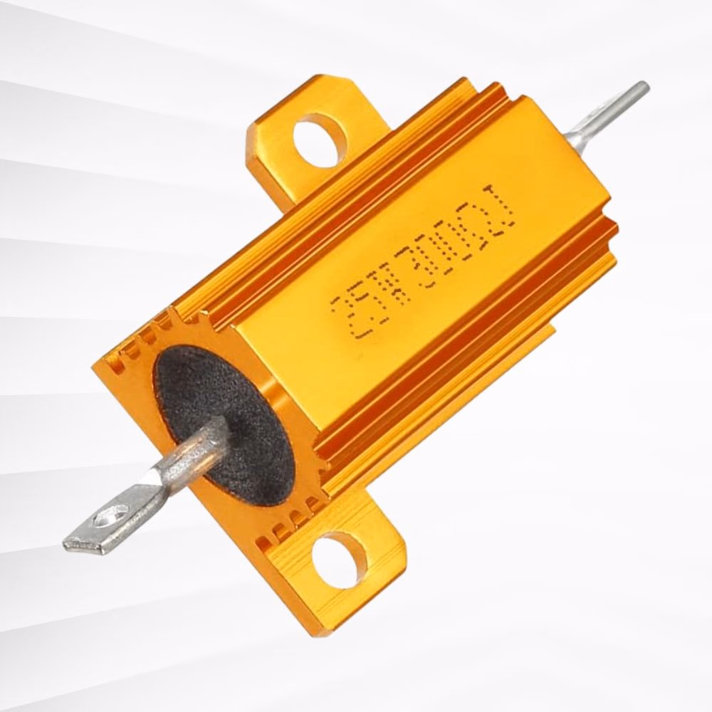
Check your inverter manual. It should specify which terminal to use for pre-charging if the procedure is required. Many manufacturers provide specific instructions for their units, though many modern inverters have built-in soft-start circuits that eliminate the need for manual pre-charging. Loosely speaking, this is the procedure: Connect the negative cable to the inverter and the battery bank or bus bar. Attach the positive wire to the inverter, mounting a 300 Ohm resistor to the free end that will eventually be attached to the battery post or bus bar. Touch the resistor to the positive battery post or bus bar for sixty seconds. This pre-charges the capacitors in a controlled manner, ensuring the arc will not occur. Remove the resistor and mount the free end of the positive wire to the positive battery post or bus bar.
Attaching Your Inverter to the Auxiliary Battery Bank
Inverters often come with wires to attach to battery terminals or a bus bar. In my experience, these wires are rated for the continuous power rating and not the surge rating. Because I prefer to err on the side of caution, I size my wires to the surge rating, meaning they will often be a higher gauge than what is provided by the manufacturer.
To select the correct size wire gauge, we must determine the maximum amperage that the batteries will pass to the inverter. To do this, divide the surge power rating value by the voltage of our battery bank. For example:
\text{ 800 W } \div \text{ 12 V } = \text{ 67 amps } Now we want to add the recommended safety margin by multiply the above value by 1.25.
\text{ 67 amps } \times \text{ 1.25 } = \text{ 84 Amps } We then estimate the length of the wire run, multiplying it by two to account for the cumulative length of both the positive and negative wires, and consult a Conductors Size (AWG) for 3% Voltage Drop table provided by the wire manufacturer. In the example below, I am consulting the chart provided by the wire manufactured Ancor. And I'm assuming the required wire run is ten feet or fewer for the 84 amps of current, rounding up to 90 amps:
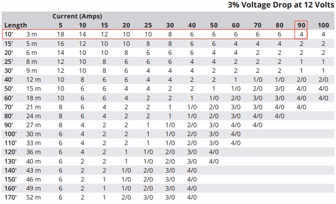
As we see above, the 10' wire length row intersects the 90 Amp column at 4 AWG. So we can confidently install a 4 AWG wire to connect our inverter to our battery bank or bus bar. This connection powers the inverter.
To find the wire gauge for amperage higher than the 100 Amp maximum provided by the Ancor wire manufacturer, I recommend Blue Sea System's Circuit Wizard calculator.
Every wire should be protected by a fuse. The fuse is designed to protect the wire. Multiply the rated wire current by a safety factor to account for variations and ensure the fuse doesn't blow during normal operation. A common safety factor is 1.25.
So in the case of the inverter above, with its 800W surge rating, the maximum current draw would be 67 amps. Your wire should be sized to handle at least 125% of this value (86A × 1.25 = 84A minimum). Since you use wire rated for 90A, the fuse should be rated close to 112.5 amps (90 amps x 1.25 = 112.5 amps). The fuse should be placed as close to the power source as practical, ideally within 18 inches.
Grounding the Inverter
Every inverter will have a grounding terminal. Grounding keeps all exposed metal (inverter case, van chassis, appliance enclosures) at the same electrical potential. This reduces the risk of shocks from small leakage currents and helps stabilize the system electrically. In AC systems, the neutral-to-ground bond (usually made inside the inverter when not on shore power) ensures breakers trip properly if a hot-to-chassis fault occurs. Without a solid ground, that fault current might flow through you if you touched the case and a grounded object (like the van frame).
Consult the user manual to size the neutral wire. Renogy recommends 14AWG for their 1000W inverter, 12AWG for their 2000W inverter, and 10AWG for their 3000W inverter. These will differ by manufacturer, so please find the recommended value for your specific make and model.
To install the ground to the vehicle chassis, as is best practice, find an area of the van that is mounted to the chassis and is relatively thick. The vertical ribbing on the van wall should suffice. Drilling through the floor and contacting the frame below is better. Scrape bare any painted metal, insert a star washer between the floor and the ground wire terminal, and screw or bolt the wire terminal into the chassis connection point. If you have already grounded your bus bar, you can terminate your inverter grounding wire on the bus bar ground bar.
How to Power 120V AC Devices With Your Inverter
Now that the inverter has been powered by the auxiliary battery bank and successfully grounded, we can use it to power 120V devices. Most inverters have a 120V outlet directly on them.
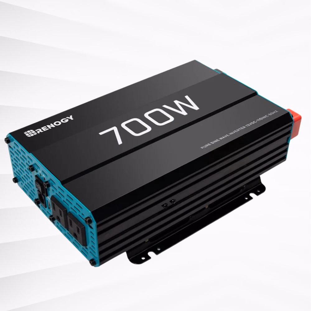
We can simply plug an electric device or power strip to the inverter and use our inverter like this.
Understanding 120V Wire
When voltage increases, amperage decreases. So when working with 120V wiring, the wire sizes will be significantly smaller than those you are used to when connecting 12V DC components. To demonstrate this, let's look at the difference in amperage running through a wire at differing voltages:
- 500W at 12V = 41.7 Amps
- 500W at 120V = 4.17 Amps
As you can see, the higher voltage significantly reduces the amperage running through wires when consuming similar power.
Also, different from working with direct current wiring is the addition of a third wire.

Each wire can be identified by its color:
- Live (Hot): Black
- Neutral: White
- Ground: Green
We determine the wire size the same way we do with DC wiring. We must know the maximum amperage passing through the wire and consult the wire manufacturer sizing table. Even though there's now three strands, we only consider the round trip length as that between the live and neutral wires. So just like sizing our DC wires, we use the run length and multiply it by two to account for the round trip distance. This is the length we use when consulting the wire manufacturer sizing table.
Powering a 120V Distribution Panel From an Inverter
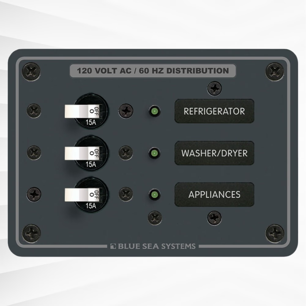
If you'd like to install 120V outlets throughout your van build, you might prefer to land the 120V power coming from the power inverter into a 120 Volt AC breaker panel, and then distribute power from individual circuits within the distribution panel to outlets, as needed. Blue Sea makes a circuit breaker for use in boats that are perfect for vans and RVs (as shown below):
To safely power a breaker panel from an inverter, choose an inverter with hard-wire AC output terminals (hot, neutral, ground). Connect these to the distribution panel, making sure neutrals and grounds are isolated per code and that each circuit leaving the panel is protected by an appropriately sized breaker or fuse.
For protection, you can add a residual-current device (RCD) or GFCI breaker on the wire leaving the inverter before they connect to the distribution panel. This device trips if live and neutral currents are unbalanced, indicating leakage to ground. Alternatively, you can install GFCI outlets on branch circuits; however, these must always be used in addition to overcurrent protection.
If the AC distribution panel capacity is significantly larger than the inverter can supply, we can install a circuit break inline as well. For example, the 3-Circuit Distribution Panel pictured above has three 15 Amp breakers included. Which means it could handle up to 45 Amps in total. A 700W inverter does not come close to providing 45 Amps. It maxes out as 5.8 continuous amps (700W/120V = 5.8 Amps). So the inline circuit breaker serves as the safety shut off in the event of a surge in power. The individual 15 Amp breakers will then functionally serve as convenient shutoffs, but they won't actually provide any meaningful protection to your wires. We could also consider changing out the 15 Amp A-Series White Toggle single Pole Circuit Breaker for a smaller amperage model. Though this will require understanding exactly what appliances you will run from each outlet and not deviating from this. If you have three 5 Amp breakers, you can still overwhelm the inverter's capacity to supply power.
From here, we land the live, neutral, and ground wires onto the distribution panel as recommended by the manufacturer. The individual circuits can then be wired to the outlets. Please consult with a licensed electrical installer to ensure all wiring is up to electrical code.
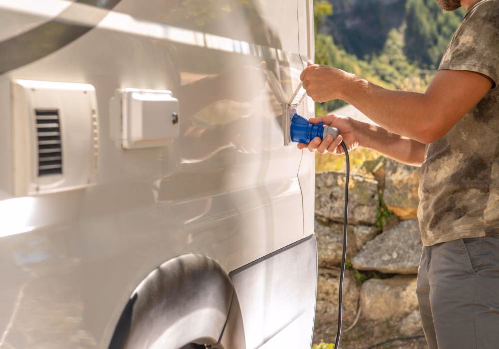
Integrating Your Inverter With Shore Power or a Generator
Some campgrounds offer electrical hook ups. So does your best friend's driveway. And some van-lifers like to carry a generator so they can create their own power. We can design our van's electrical system to take advantage of this in several differing ways.
Charge Your Battery and Carry On As Usual
A simple approach to taking advantage of this shore or generator power is to use the shore power connection point to power a battery charger. The battery charger can be hard-wired via an M10 or M6 connector directly to the bus bar. This will charge the auxiliary batteries when plugged into the grid and the inverter will continue to run off the battery bank as usual.
In my van, I have a Noco Genius 5 Amp charger like the model pictured below:
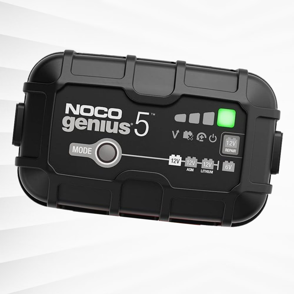
Charging my 400 amp-hour battery bank over a sixteen-hour period at a campground provides 80 Amp-hours of charge to my auxiliary battery bank. In addition to my solar, this has always been more than adequate—and, honestly, not even necessary. But it offers a peace of mind. Most campgrounds have 30-amp or 50-amp services, in addition to a standard 15-amp household outlet alongside the RV-specific connectors. So if you'd prefer a higher charging rate than 5 Amp, it's entirely possible. Noco Genius battery chargers range from 1 Amp to 50 Amp and have a Lithium charge mode on all chargers. This is what I use and I can confidently recommend it.
Bypass Your Inverter By Installing a Transfer Switch
An inverter transfer switch is a device that automatically switches the source of AC power feeding your circuits.
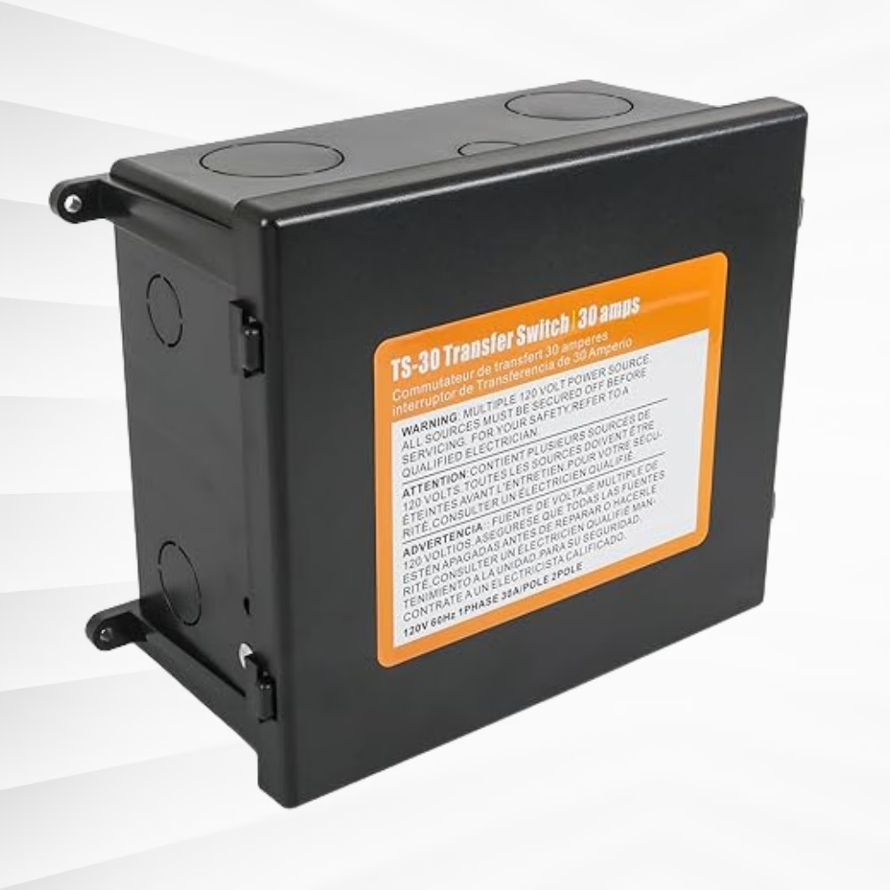
The switch will detect when the van is plugged into shore power and begin powering your AC circuits directly from shore power, completely bypassing the installed inverter. It does this by being installed between the inverter and the AC distribution panel. The shore power is hard-wired into the transfer switch.
Fortunately, many modern inverters have a transfer switch included internally. Follow the manufacturer installation instructions to hook up shore power to the inverter, as the recommendations will vary by manufacturer.
Bypass Your Inverter While Charging Your Auxiliary Battery Bank
Another option is an inverter charger. An inverter charger is a dual-purpose device that combines two essential functions for power systems: (1) Converts DC power into AC power (2) Charges the battery bank when shore power is available. When shore power is available, the device charges your batteries and can simultaneously power your AC loads
Moving Forward From Here
There's more to a van's electrical installation than just the getting your inverter installed. And we're building out our knowledge base to cover every aspect of this process, from design to long term maintenance. Please review our current articles related to van electrical installation:
For information on sizing your wires, please see our article Sizing Wire For Your Van Build: A Beginner's Guide
And for more information regarding solar installation, please review our article, Camper Van Solar Installation Guide For Complete Beginners